Garrattfan's Modelrailroading Pages
OO9 NGG16
Chapter 05 Electrical pickup and final unit assembly
Unit 1: April 30, 2009 till .... Unit 2: not started yet Though seemingly tiny the electrical pickup is nevertheless a critical component. Not only to make the motors runs, but also in the sense that bad pickup arrangement may disturb the proper operation of the units. Well, the manual is very clear about how to install so just do it that way, and it will work. |

Rear quarter view. A narrow brass bridge is soldered between the the frames. The current conducting copper clad paxolin is glued onto it with epoxy. I arranged the wipers a little different, but that is of no importance. As per the instructions I soldered the wiring with 180, 145 and 70 degrees solder respectively (5.6) |

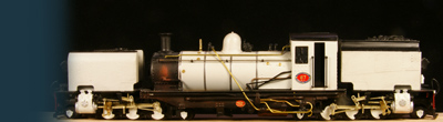
Topside view It gives you an impression just how cramped and stuffed a unit gets and how tight clearances are. I had to bend the cylinders a little outwards to get sufficient clearance. It is not conspicuous once installed under a tank. |
General overview Two things that are not in the instructions are really important. 1. Make sure the wipers to the leading wheel set duck under the valve gear bracket with sufficient clearance. If one touches the frame is no longer electrically neutral, if two touch you have a shortcut. 2. Make sure the polarity of the wiring is correct, so the locomotive runs the right way. Having arrived at instruction 5.8 (fixing the lubricator and the vacuum pipe hose) I found that the surface of running plate was nicely even at the front edge. I filled it with Tamiya Putty and left it to set for 24 hours. |
 |
In the mean time I worked on the leading and trailing trucks. I cut all four trucks out of the etch and filed etch rims away. A folded one leading and one trailing truck and soldered the folds as per the instructions. |

Chamfer the axle holes. Not in the instructions but certainly useful is chamfering the pickup holes for the axles. It will help fitting the axle in. Rule of thumb when chamfering: the drill must be at least twice the size of the hole. Chamfer just lightly. |

A first setback was soon discovered when I trial fitted the leading truck. Its fits was not even close. I set it aside to work out a solution |
The trailing bogie was less problematic. With some tweaking it simply fit. On the internet I read on several occasions that the trucks are fiddly to make the run well. They are prone to derailment at every possible (and impossible) occasion because there is no weight on them. Room is limited and I didn't want to disturb the fragile looks of them by heavily loading them with lead. My solution is simple and inspired by Iain Rice's methods of springing trucks and bogies (see his book Locomotive Chassis Construction) I soldered a 0,3 mm steel spring wire on the back bottom of the truck, bent it over the axle towards the main frame and fit it in a 0,5mm hole in the middle of the rear chassis cross member (12). The steel spring is so adjusted that it presses the truck down, effectively springing the trailing truck. The wire is NOT soldered in the hole of the cross member giving the truck freedom of movement up and down (about 1 mm) and right and left. Soldering would nail it down rock solid. It took a few days to work out a suitable solution for the front truck. More than the rear truck this one is prone to derailment and I want it to be sprung both vertically and horizontally. There is hardly room for any springing at all. I firgured out various solution but neither would work. I finally made this version sacrificing the coupler mounting. |

The spring consists again of 0,3 mm steel spring wire. A bit stiff, but it will do. The part with the hole to connect the truck to the frame had various problems. As can be seen from the previous photo of the truck its hole was about a mm too far back pushing the truck too far ahead. I cut it off, soldered a new strip of brass sheet to the truck and drilled a hole on the suitable place. I also added a piece of cast bars of 1,5 mm thickness, drille a hole through as the truck would otherwise end up way too high |

This is the end result The spring being loosely fitted through an extra piece of brass on the mainframe with a 0,5 mm hole in it. The wheelset is pressed a little too low, as to ensure that when the truck is fully loaded the pressure will keep the truck on the rails. Springing allows it to move up about 0,5-1,0 mm. Sideways the truck will move 1,0-1,5 mm, suffcient for really tight curves. |


Sign my
GuestBook